Cover Design
This post talks about the different layers and the program logic behind the way it works.
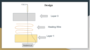
Layer 1 will be constructed out of fiberglass cloth. It acts as an insulator of heat, not allowing the car to get heated. Heating wires (Layer 2) is above the insulation layer which serves as the heating element for the cover. Layer 1 and 2 are going to be connected using adhesive tape. The tape is strong enough to withstand the heat and also avoid the intersection of the heating wires, eventually preventing a short circuit. The tape is also insulated, not allowing the heat to pass through. Layer 3 has fabric until tested which is a conductor of heat, allowing heat to pass through it, eventually heating the snow. It is connected to the heating wires using a conductive adhesive tape.
Program Logic
When the button is turned on, the sensor is set up to communicate with two GPIO (General Purpose Input/Output) pins, which are initially activated. A stopwatch function is employed: it starts timing when the sensor emits a wave and stops when it receives the wave’s reflection. This timing data is then used to calculate the distance between the sensor and the object reflecting the wave.
The system operates with three states based on the measured distance:
-
State 2 (Heating On): When the sensor detects an object at a distance greater than 50mm (indicating no significant snow accumulation), the system enters State 2. This triggers the relay, which is connected to two other GPIO pins on the Raspberry Pi. The relay connects the 12V power supply to the heating wires, causing them to heat up.
-
State 1 (Intermediate): When the sensor detects an object at a distance between 15mm and 50mm, the system enters State 1. In this state, the heating wires’ status depends on the previous state:
-
If the previous state was State 0, the relay remains deactivated, keeping the heating wires off.
-
If the previous state was State 2, the relay remains activated, keeping the heating wires on.
-
State 0 (Heating Off): When the sensor detects an object at a distance of less than 15 mm, the system enters State 0. This deactivates the relay, disconnecting the 12V power supply from the heating wires and turning them off.
This setup ensures that the heating system is only activated when needed, based on the sensor’s distance measurements and the system’s previous state, providing an efficient way to manage the heating wires and conserve energy.

This image depicts the circuit when the sensor detects snow above 150mm, causing the relay to turn on. The sensor continues to take readings.

This image illustrates the circuit when the sensor does not detect snow above 150mm, meaning the relay is turned off. However, the sensor continues to take readings.
Microcontroller (Raspberry pi) with other materials & tools Sensor building process